
Motivation
The main reason for designing this was that I came across another PCB business card that was poorly executed and very expensive to make, so I decided to make a better one. I wanted one that had Snake because Snake is awesome, and a two-player game that you can play with perhaps a potential employer. It should be affordable and assembled at the PCB manufacturer.
Design choices
Business card aspects
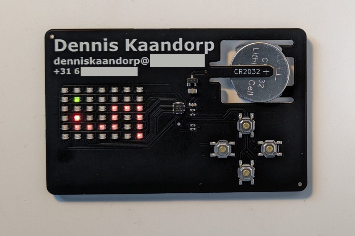
- The PCB has the same dimensions as a credit card.
- It has my email and phone number on the front (behind the black tape for privacy)
- It has a QR code with a direct link to my LinkedIn page.
- It required some basic electronics skills to design, I don’t expect any potential employer to be amazed by it in my industry but it has some features that I think are nicely executed.
Power source
It should be battery-powered for convenience. There are very few low-profile battery holders that do not add significant thickness to a business card. There are through PCB solutions such as the Keystone 1057 that sit inside a cutout in the PCB, but these are both expensive (~2€) and still rather thick.
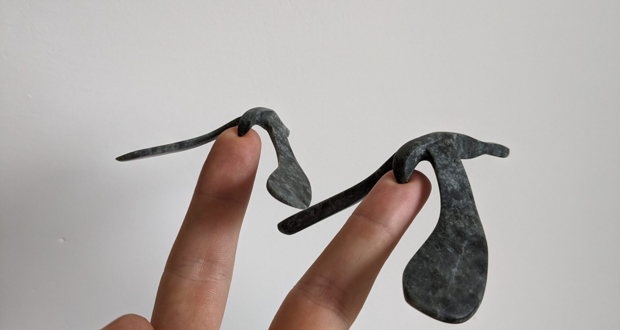
Using the PCB as the battery holder by means of flexible arms is something I’ve seen used as a comment on Hackaday, and does not add any thickness or costs to the PCB. I’ve designed the cutout using simulation to determine the amount of force required to insert the battery into a 0.8mm thick PCB. The resulting geometry is sturdy enough so a battery doesn’t fall out when you shake the PCB, but the force required to insert the battery is small enough that it doesn’t feel like it’s about to break.

A CR2032 battery has a capacity of about 230mAh, I’ve measured the businesscard to draw 4-5mA so it should last about 50 hours which sounds more than sufficient for a business card.
A mosfet is placed at the input for reverse polarity protection.
LED matrix
The grid size is determined by the gameboard for Connect 4, which is 6×7 for a total of 42 dual-colour LEDs. Multiplexing is required to drive these 84 LEDs with a minimum amount of hardware. Charlieplexing would require a minimum of 10 GPIO pins but would result in very difficult routing. A hybrid between classical multiplexing and Charlieplexing is used for a total of 13 pins:

The issue with Charlieplexing using microcontroller pins is the voltage drop over the pins, resulting in ~2.2V LED voltage when supplied with a 3V CR2032. I’ve looked through all dual colour LEDs in the JLC parts library to find a part that had low forward voltage for both colours: XL-1615SURSYGC.
Microcontroller
I wanted an affordable microcontroller that is easy to program and has at least 17 GPIO pins. I decided to use the attiny1616 which is more than capable for this application, this was the cheapest in-stock part that I could find from a manufacturer that I recognized.
The screen is updated using an interrupt timer which took the longest time to find out how to correctly use because there is little documentation:
ISR(TCB0_INT_vect) {
  TCB0.INTFLAGS = TCB_CAPT_bm;                        // Clear the interrupt flag
  updateScreen();
}
void setup() {
  TCB0.CCMP = 400;                                    // Set period
  TCB0.CTRLA = TCB_CLKSEL_CLKDIV1_gc | TCB_ENABLE_bm; // Enable timer, divide by 1
  TCB0.CTRLB = 0;                                     // Periodic Interrupt Mode
  TCB0.INTCTRL = TCB_CAPT_bm;                         // Enable interrupt
}
The remaining code is straightforward.
Cost overview
For the prototype I’ve only ordered 5 pieces, which does increase the price per PCB a bit:
| PCB | $0.40 | 1 | $0.40 |
| ATTINY1616 | $0.85 | 1 | $0.85 |
| LED | $0.0089 | 42 | $0.37 |
| Switch | $0.0146 | 4 | $0.06 |
| Mosfet | $0.0884 | 1 | $0.09 |
| Resistors and capacitors | 6 | $0.02 | |
| Total | $1.79 |
| Assembly + stencil | $11.16 |
| Assembly discount | -$9.00 |
| Extended component fee | $6.00 |
| Shipping (slow) | $4.06 |
| Taxes | $4.45 |
| Total: | $16.67 |
| Total for 1 PCB: | $3.33 |
Total price per PCB: $5.12. For a larger order of >25 pieces, it would be ~$3.50 each.
Improvements
- Next time I’d pay attention to which registers the pins are connected to, which makes programming easier and more efficient.
- Order a nicer colour PCB. The combination of 0.8mm thickness, assembly and a nice blue colour would be about $20 more expensive so I picked green for the prototype.
- Remove the order number and align the tooling holes.
- Change corner radius to 3mm to match credit cards.


Schematic:

PCB layout:

Any chance you could post the source code for the attiny? Trying to make something similar and haven’t really messed around with charlieplexing
I wasn’t planning on posting the entire source code since I just quickly threw it together and it isn’t very clear. If you search for “Charlieplexing arduino” you get many excellent explanations with clear diagrams that will help you much more than my code will.