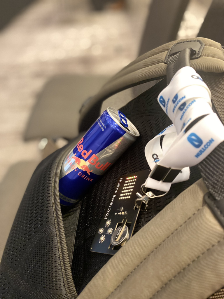
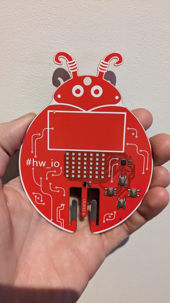
After my PCB business card was featured on hackaday.com, on Instagram, and even on twitter on a thread with Dave Jones from the EEVBLOG. (And I’m pretty sure they even mentioned the battery holder on their podcast The Amp Hour.) I was contacted by Antriksh from Payuta that organizes hardware security conferences such as Nullcon and Hardware.io, with the question if I could make my design into conference name badges. The first one was rushed due to the timing, so was just a change of the logo’s etc. but the second one for Hardware.io USA was designed to match their conference logo.
The main reason for designing this was that I came across another PCB business card that was poorly executed and very expensive to make, so I decided to make a better one. I wanted one that had Snake because Snake is awesome, and a two-player game that you can play with perhaps a potential employer. It should be affordable and assembled at the PCB manufacturer.
Design choices
Business card aspects
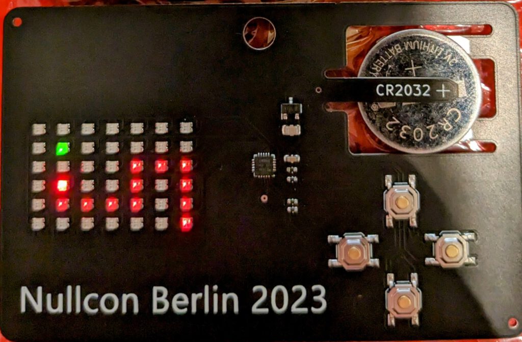
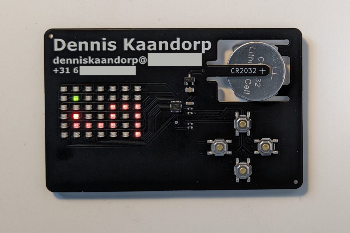
The PCB has the same dimensions as a credit card.
It has my email and phone number on the front (behind the black tape for privacy)
It has a QR code with a direct link to my LinkedIn page.
It required some basic electronics skills to design, I don’t expect any potential employer to be amazed by it in my industry but it has some features that I think are nicely executed.
Power source
It should be battery-powered for convenience. There are very few low-profile battery holders that do not add significant thickness to a business card. There are through PCB solutions such as the Keystone 1057 that sit inside a cutout in the PCB, but these are both expensive (~2€) and still rather thick.
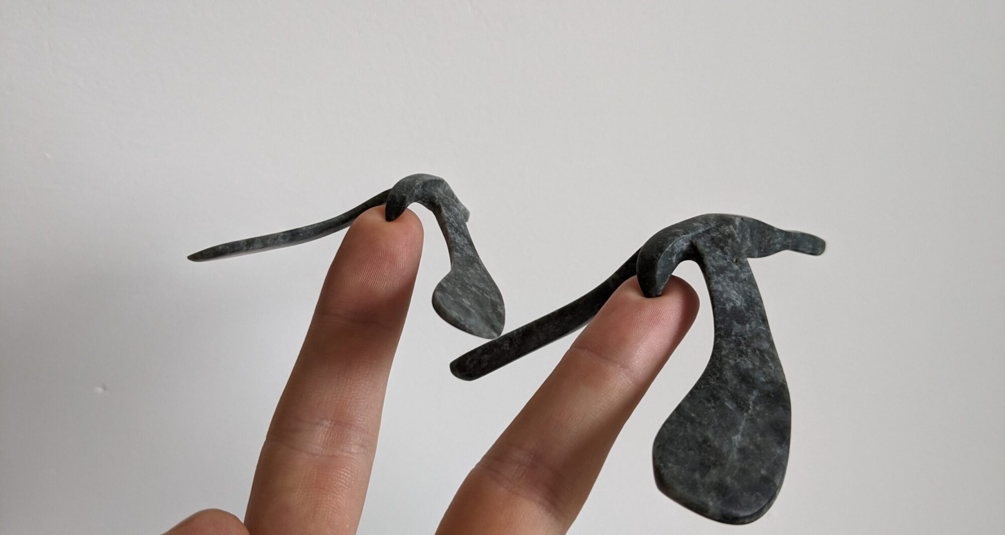
Using the PCB as the battery holder by means of flexible arms is something I’ve seen used as a comment on Hackaday, and does not add any thickness or costs to the PCB. I’ve designed the cutout using simulation to determine the amount of force required to insert the battery into a 0.8mm thick PCB. The resulting geometry is sturdy enough so a battery doesn’t fall out when you shake the PCB, but the force required to insert the battery is small enough that it doesn’t feel like it’s about to break.
The tabs are 19mm long and 4mm wide. Full
A CR2032 battery has a capacity of about 230mAh, I’ve measured the businesscard to draw 4-5mA so it should last about 50 hours which sounds more than sufficient for a business card.
A mosfet is placed at the input for reverse polarity protection.
LED matrix
The grid size is determined by the gameboard for Connect 4, which is 6×7 for a total of 42 dual-colour LEDs. Multiplexing is required to drive these 84 LEDs with a minimum amount of hardware. Charlieplexing would require a minimum of 10 GPIO pins but would result in very difficult routing. A hybrid between classical multiplexing and Charlieplexing is used for a total of 13 pins:
The issue with Charlieplexing using microcontroller pins is the voltage drop over the pins, resulting in ~2.2V LED voltage when supplied with a 3V CR2032. I’ve looked through all dual colour LEDs in the JLC parts library to find a part that had low forward voltage for both colours: XL-1615SURSYGC.
Microcontroller
I wanted an affordable microcontroller that is easy to program and has at least 17 GPIO pins. I decided to use the attiny1616 which is more than capable for this application, this was the cheapest in-stock part that I could find from a manufacturer that I recognized.
The screen is updated using an interrupt timer which took the longest time to find out how to correctly use because there is little documentation:
ISR(TCB0_INT_vect) {
  TCB0.INTFLAGS = TCB_CAPT_bm;                        // Clear the interrupt flag
  updateScreen();
}
void setup() {
  TCB0.CCMP = 400;                                    // Set period
  TCB0.CTRLA = TCB_CLKSEL_CLKDIV1_gc | TCB_ENABLE_bm; // Enable timer, divide by 1
  TCB0.CTRLB = 0;                                     // Periodic Interrupt Mode
  TCB0.INTCTRL = TCB_CAPT_bm;                         // Enable interrupt
}
The remaining code is straightforward.
Cost overview
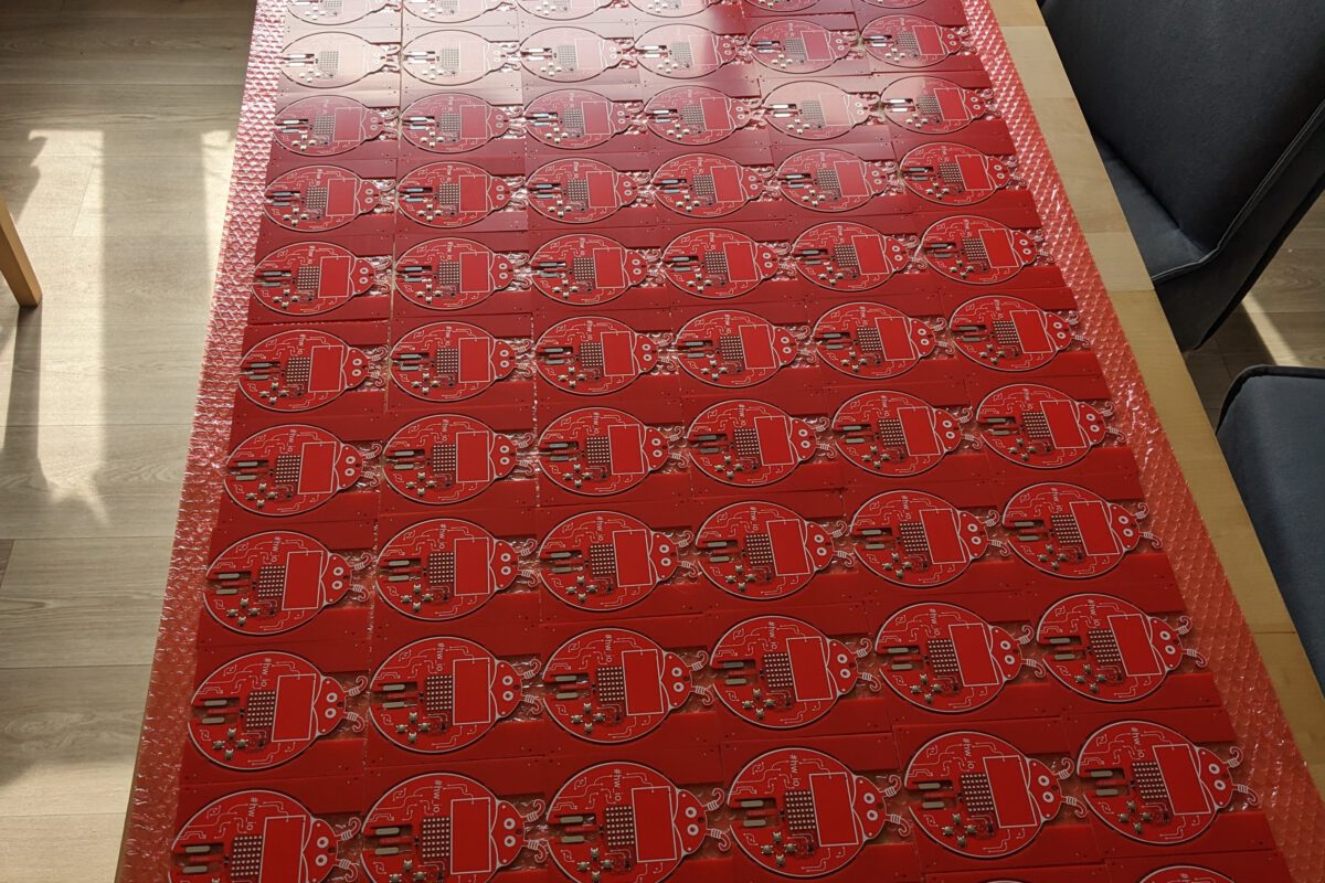
For the prototype I’ve only ordered 5 pieces, which does increase the price per PCB a bit:
PCB
$0.40
1
$0.40
ATTINY1616
$0.85
1
$0.85
LED
$0.0089
42
$0.37
Switch
$0.0146
4
$0.06
Mosfet
$0.0884
1
$0.09
Resistors and capacitors
6
$0.02
Total
$1.79
Assembly + stencil
$11.16
Assembly discount
-$9.00
Extended component fee
$6.00
Shipping (slow)
$4.06
Taxes
$4.45
Total:
$16.67
Total for 1 PCB:
$3.33
Total price per PCB: $5.12. For a larger order of >25 pieces, it would be ~$3.50 each.
Improvements
Next time I’d pay attention to which registers the pins are connected to, which makes programming easier and more efficient.
Order a nicer colour PCB. The combination of 0.8mm thickness, assembly and a nice blue colour would be about $20 more expensive so I picked green for the prototype.
Remove the order number and align the tooling holes.
Change corner radius to 3mm to match credit cards.
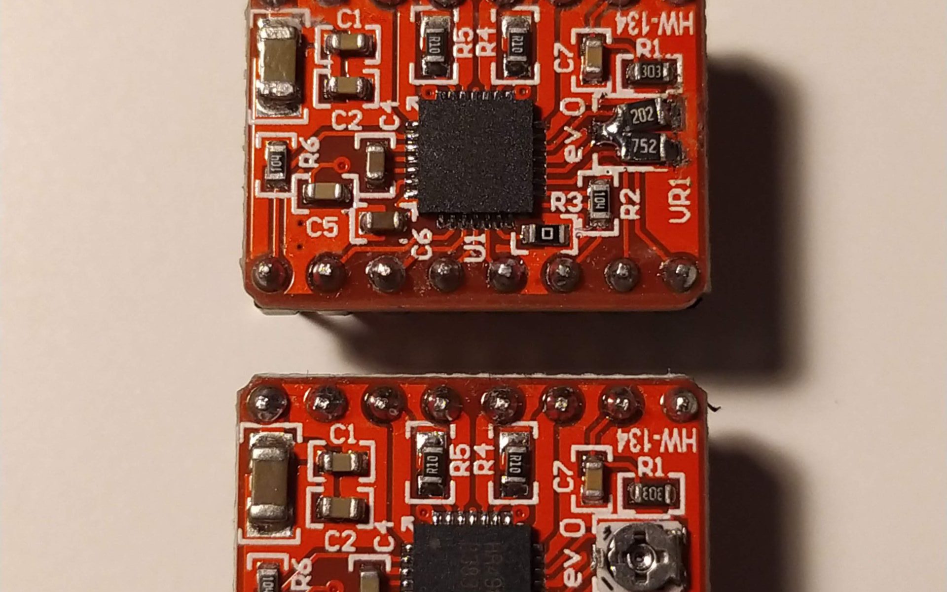
2 out of the 4 stepper drivers I recently received arrived broken. A quick check with a multimeter showed that the potentiometers used to set the maximum current were defective. Without time to wait for replacements, and without this package of smd potentiometer on hand, I decided to just solder two 0805 resistors in place.
The values are calculated using where is the output voltage of the resistive divider consisting of the potentiometer and R1(30kΩ), is the maximum current and is the current sense resistor (R4 and R5 in the image below; 0.1Ω).
Broken potentiometers; probably a manufacturing error.Top: repaired stepper driver set at ~1.2A; Bottom: original stepper driver
The effect of TL smoothers is very dependent on the type of 3D printer, in the case of the Creality Ender 3 pro there is a noticeable difference when adding TL smoothers on the X and Y axis, adding additional smoothers on E and Z had no noticeable difference and doesn’t really fit inside the control board enclosure.
Before adding TL-smoothersAfter adding TL smoothers on X and Y axis
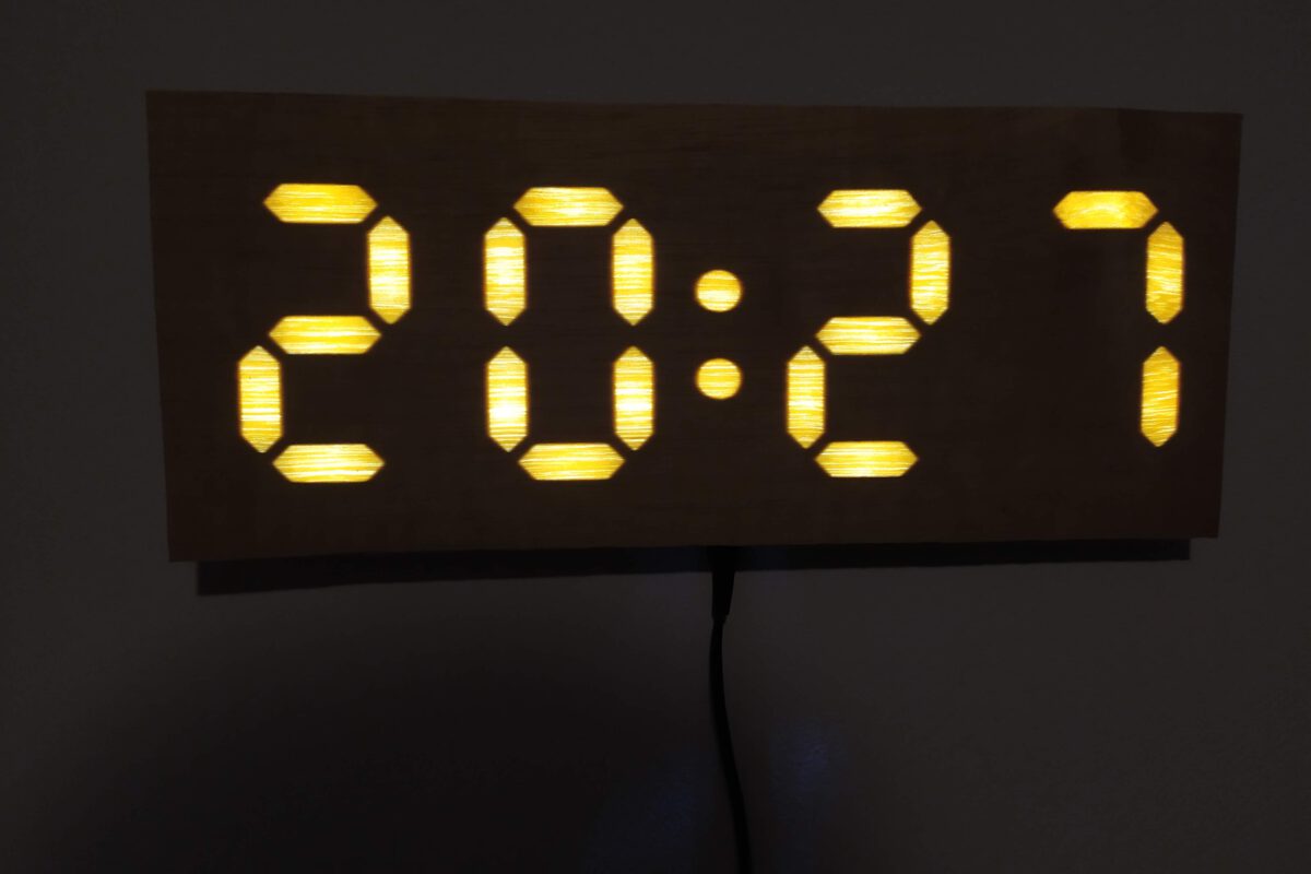
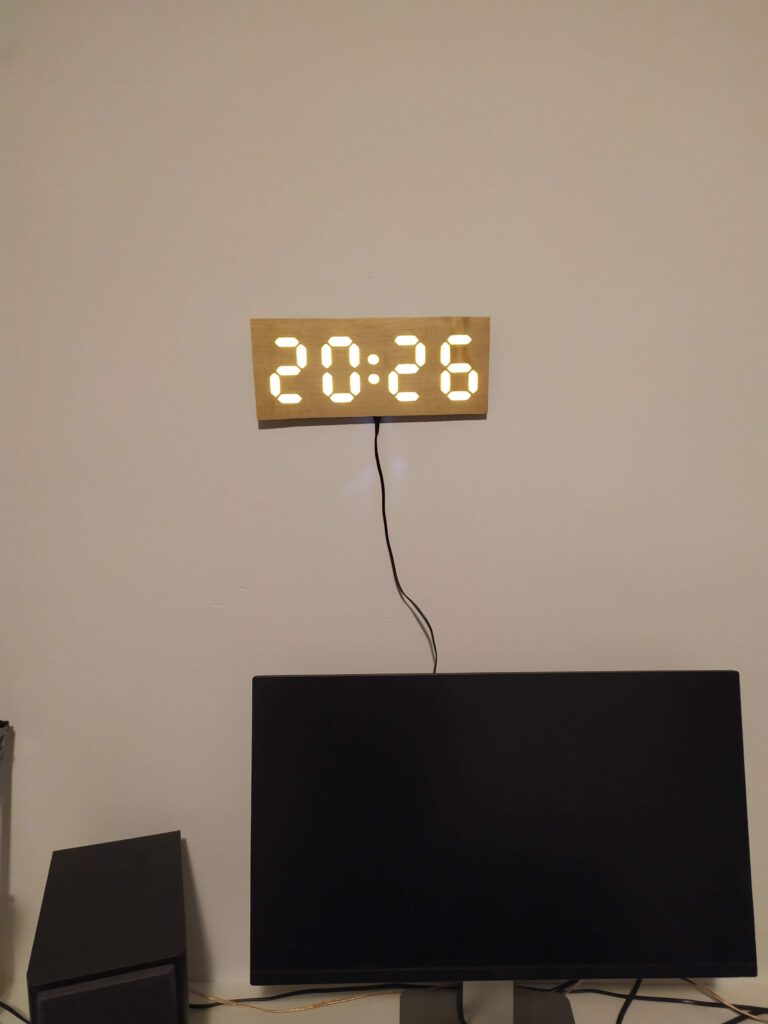
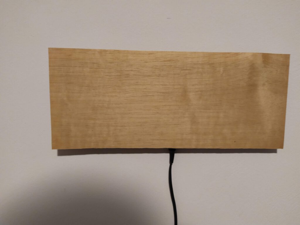
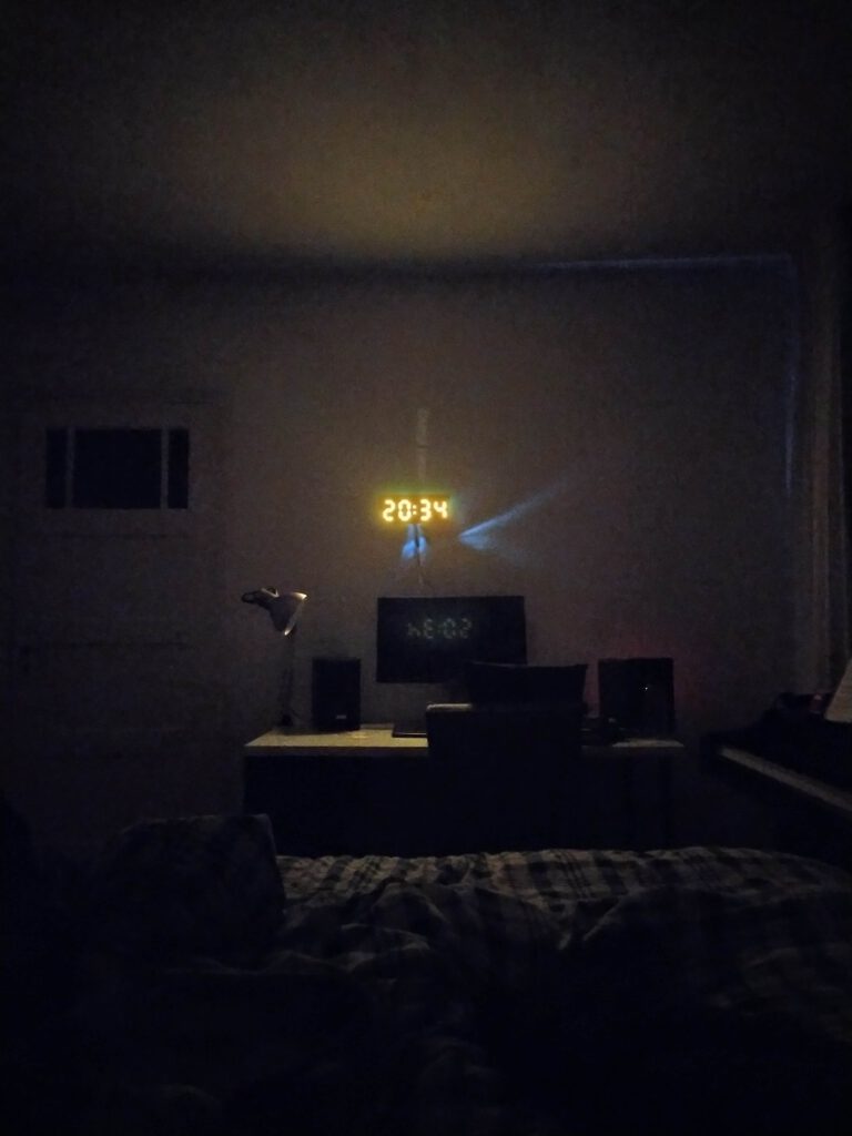
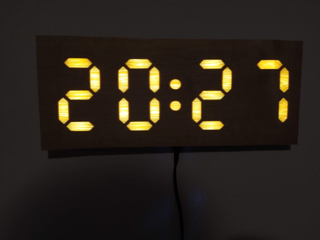
I had some food fineer from another project, and wanted a clock for in my bedroom that automatically adjusts the intensity based on the ambient light intensity.
I’ve designed the PCB so that 4 of them interlock, with 3d printed 7 segment dividers and wood fineer glued to that. The entire thing is driven from an ESP8266 to connect to a network clock with backup internal time-keeping. The pictures below are before the light intensity was fixed.
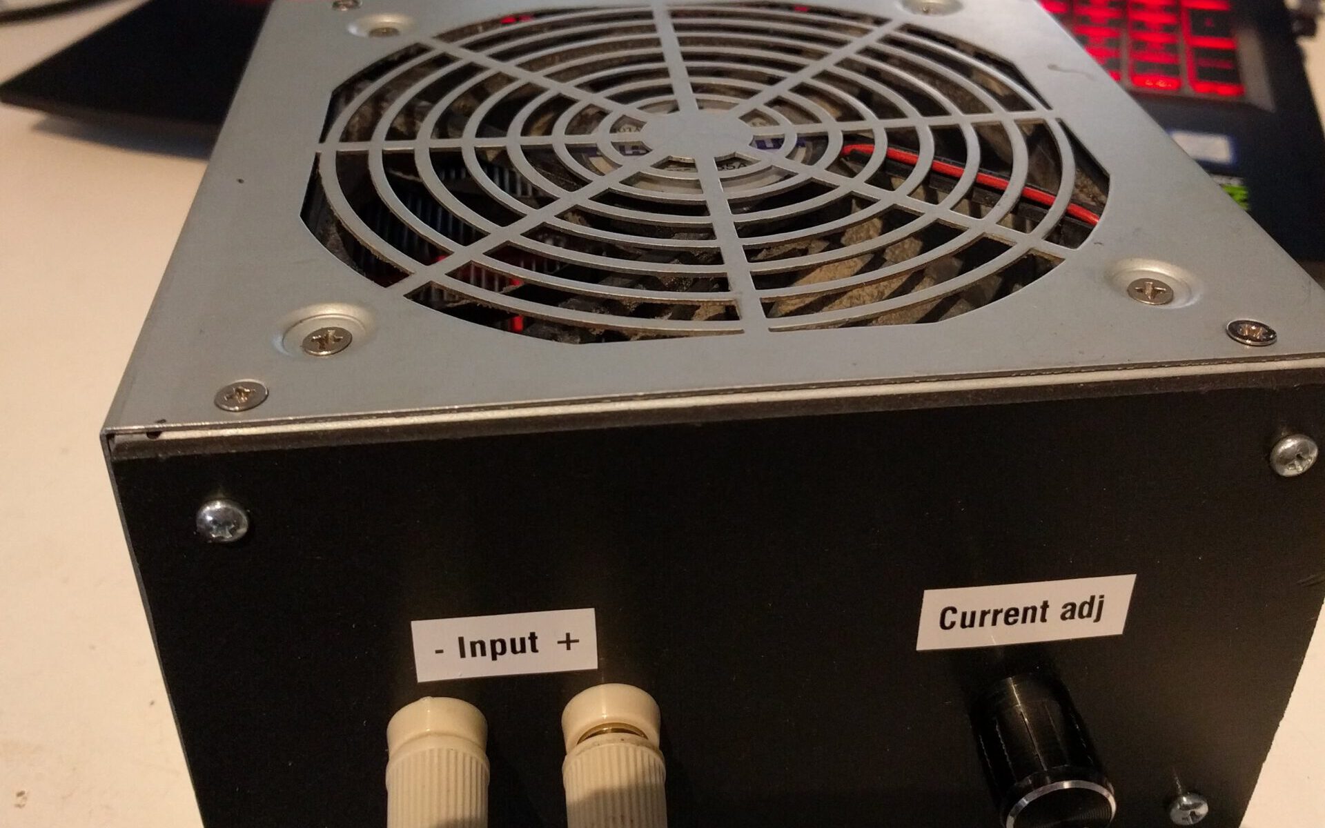
I needed a way to test a power supply I got from eBay, the issue I was facing was that it was a 48V7.5A power supply, so just hooking up a couple of resistors or bulbs wasn’t going to work. I figured this was a good excuse to finally make myself an electronic load out of parts from my scrap drawer.
Quite a straightforward design, 10 parallel mosfets (IRFZ44N), each connected to their own opamp(LM358) with a current shunt resistor (0R33 1W) and a 10 turn potmeter to set the desired load current.
I just got myself an infrared thermometer, so I also measured the temperature increase for different loads with different heatsinks to get an idea of the power I can put into them. (This could also be found in every datasheet, however I salvaged them from my junk drawer.)
Not the best setup, but this is the actual fan that will be in the enclosure with one of the actual heat-sinks, so it should give an idea of what I can expect.
Blowing or sucking:
I had a discussion with a fellow student about whether it would be more effective to face the fan inwards or outwards, my thoughts were that drawing the hot air away would be more effective, his idea was that perhaps the nonlinear flow you get from blowing against it might help.
Best way to settle this was to just measure it, so I attached a thermocouple to one of the heat-sinks and ran it over a range of currents, let the temperature settle for about 10 minutes before continuing.
This shows a 0.23°C/W increase for an inward flow direction and a 0.11°C/W increase for an outward flow direction. (24°C ambient temperature, 12V/0.35A PSU fan)
Very simple circuit, in my case 5 of these circuits in parallel.
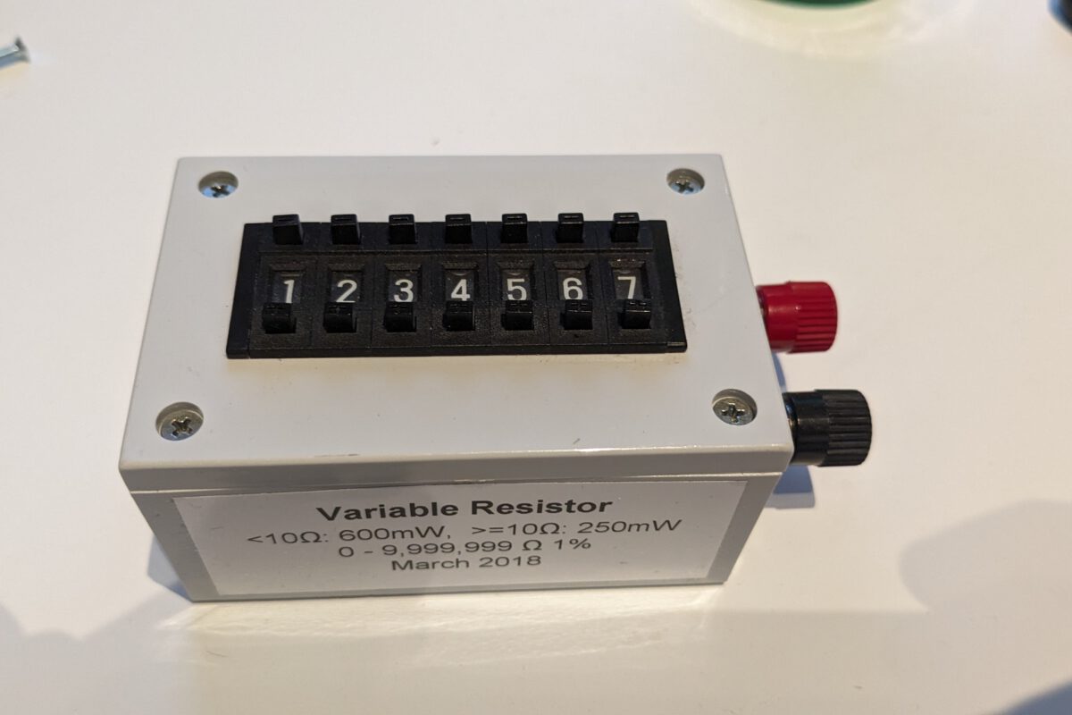
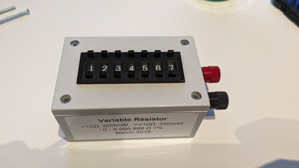
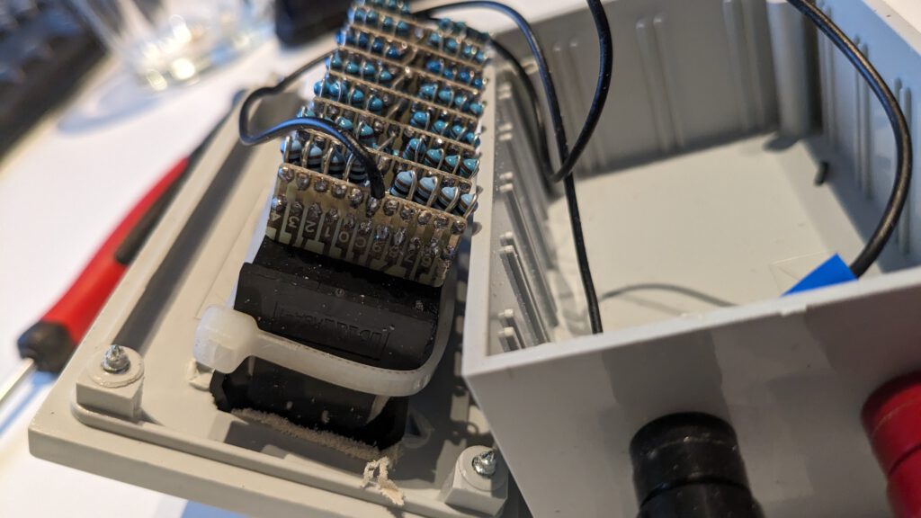
Inspired by an EEVBLOG post, I made a variable / decade resistor box. It consists out of 7 thumbwheel switches with resistors soldered across every position.


 where
where  is the output voltage of the resistive divider consisting of the potentiometer and R1(30kΩ),
  is the maximum current and
  is the current sense resistor (R4 and R5 in the image below; 0.1Ω).