
I needed a way to test a power supply I got from eBay, the issue I was facing was that it was a 48V7.5A power supply, so just hooking up a couple of resistors or bulbs wasn’t going to work. I figured this was a good excuse to finally make myself an electronic load out of parts from my scrap drawer.
Quite a straightforward design, 10 parallel mosfets (IRFZ44N), each connected to their own opamp(LM358) with a current shunt resistor (0R33 1W) and a 10 turn potmeter to set the desired load current.
I just got myself an infrared thermometer, so I also measured the temperature increase for different loads with different heatsinks to get an idea of the power I can put into them. (This could also be found in every datasheet, however I salvaged them from my junk drawer.)

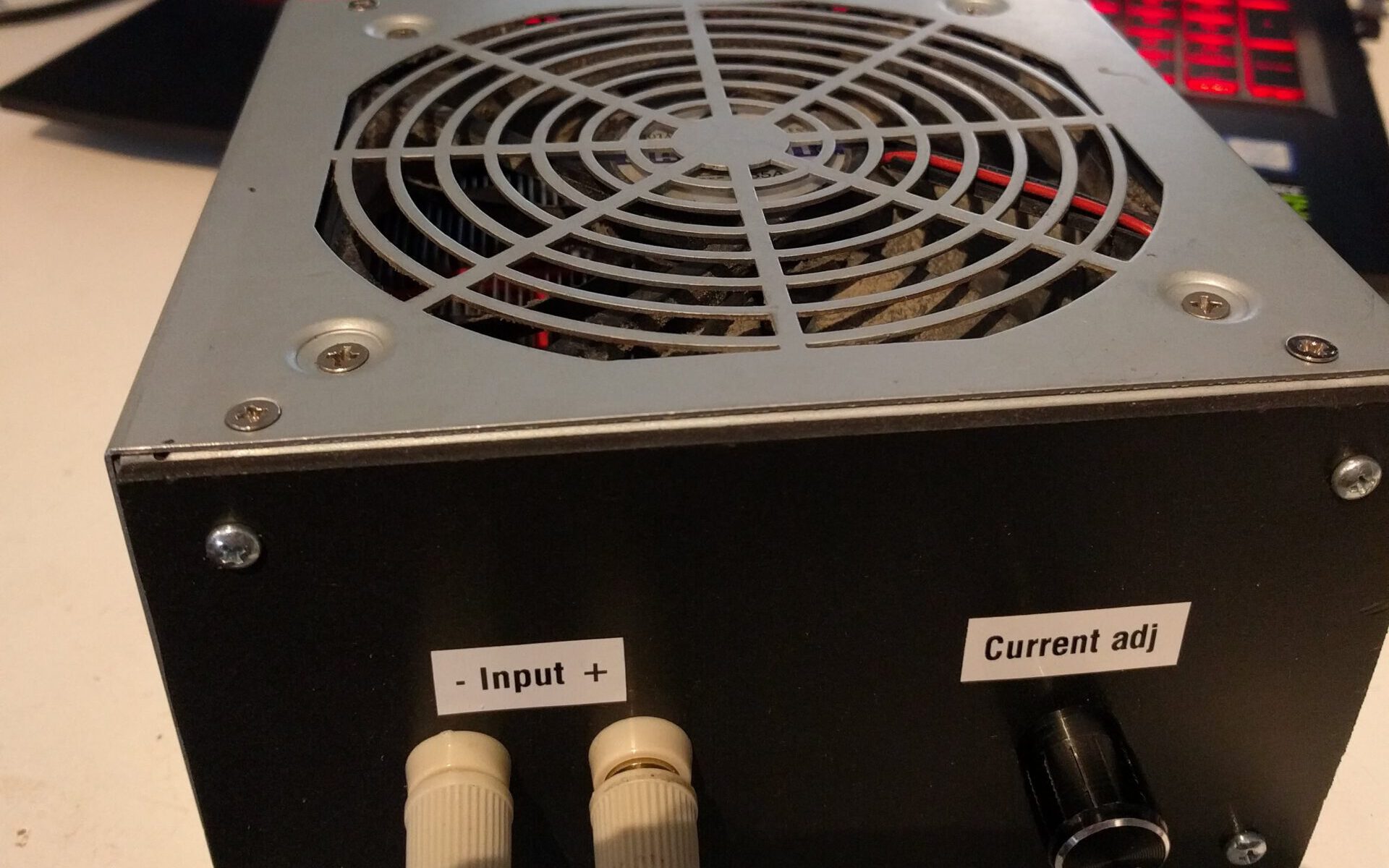
Not the best setup, but this is the actual fan that will be in the enclosure with one of the actual heat-sinks, so it should give an idea of what I can expect. 
Blowing or sucking:
I had a discussion with a fellow student about whether it would be more effective to face the fan inwards or outwards, my thoughts were that drawing the hot air away would be more effective, his idea was that perhaps the nonlinear flow you get from blowing against it might help.
Best way to settle this was to just measure it, so I attached a thermocouple to one of the heat-sinks and ran it over a range of currents, let the temperature settle for about 10 minutes before continuing.

This shows a 0.23°C/W increase for an inward flow direction and a 0.11°C/W increase for an outward flow direction. (24°C ambient temperature, 12V/0.35A PSU fan)

Very simple circuit, in my case 5 of these circuits in parallel.